Notifier M721E | Dual Input Single Output Module | Built-in Short Circuit Isolator
£122.88 (inc VAT: £147.46)
Summary
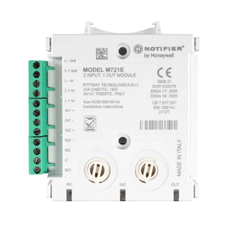
The Notifier M721E Dual Input – Single Output Module is a microprocessor-controlled interface device that provides comprehensive monitoring and control capabilities for fire alarm systems. This addressable module monitors two independent input circuits from normally open contact fire alarm and supervisory devices while simultaneously providing a single pole changeover relay output rated at 2A for controlling auxiliary equipment such as fire shutters, dampers, and notification appliances.
Each channel features dedicated tri-colour LED indicators that provide clear visual status information for both inputs and the relay output. The IN1 and IN2 LEDs pulse green during normal polling and switch to steady red during alarm conditions, while yellow indication signals open circuit faults. The OUT LED pulses green during polling and illuminates steady green when the relay contacts are energised, enabling technicians to quickly assess system status without specialised test equipment.
The module’s compact design incorporates built-in DIN rail mounting brackets alongside compatibility with standard electrical back boxes and the dedicated M200E-SMB surface mounting enclosure. Both the address selection rotary switches and status LEDs are accessible from multiple sides without removing enclosure covers, significantly reducing installation and maintenance time. Built-in short circuit isolators can be individually enabled or disabled to optimise loop configuration for high-current applications while maintaining loop integrity.
Features
- Compatible with Notifier CLIP and Advanced Protocol fire alarm control panels
- Dual channel monitoring of normally open contact devices
- Single pole Form C changeover relay output for auxiliary device control
- Three tri-colour LED indicators (green/red/yellow) for comprehensive status display
- Latched and analogue supervision modes for input channels
- Built-in short circuit isolator with individual enable/disable capability
- Rotary decade address switches for direct address selection from 01-159
- Automatic address assignment for second input and output channels
- Module occupies three consecutive loop addresses
- Enlarged light pipes visible from two sides without cover removal
- Plug-in screw terminals supporting conductors up to 2.5mm²
- Multiple mounting options including surface box, DIN rail and panel mount
- Integrated DIN rail brackets for 35mm x 7.5mm standard rail
- Compatible with M200E-SMB surface mounting box (IP44 rating)
- Quick connector terminals for rapid installation and maintenance
- Laser engraved labelling for permanent product identification
- Powered directly from two-wire loop with no additional power required
- Continuous analogue supervision monitors circuit resistance
- Automatic device type identification to control panel
- 18kΩ end-of-line resistors included for supervised operation
FAQs
What addressing considerations apply to the M721E module?
The M721E automatically occupies three consecutive loop addresses. The address selected via the rotary switches refers to the first input channel (IN1), with the module automatically assigning the next address to the second input (IN2) and the following address to the output channel. Consequently, addresses 158 and 159 are invalid on systems using 159-address capacity, and addresses 98 and 99 are invalid on panels limited to 99 addresses. If invalid addresses are selected, the module will not respond to panel polling.
Can the built-in short circuit isolators be disabled on the M721E?
Yes, the short circuit isolators can be wired out of the loop circuit when required for high-current applications such as sounder circuits. To bypass the isolator, connect the loop output positive to terminal 5 rather than terminal 2. This configuration is beneficial when multiple high-current devices are connected to the loop, as it prevents the isolators from activating due to normal load current rather than actual short circuit conditions.
What supervision capabilities does the M721E provide for input circuits?
The M721E offers both latched and analogue supervision modes. Latched supervision provides three distinct states: normal, open circuit (indicated by yellow LED), and combined alarm/short circuit (indicated by red LED). Analogue supervision continuously monitors the supervised circuit and returns a signal proportional to the circuit resistance, enabling the control panel to detect gradual degradation of wiring integrity. When using supervised mode, an 18kΩ end-of-line resistor should be wired in series with each monitored device.
What types of loads can the M721E relay output control?
The M721E relay output is rated for 2A at 30VDC resistive loads and provides a single pole Form C changeover contact. For resistive loads such as indicator lamps or low-power control circuits, the relay can be used directly. However, when switching inductive loads such as solenoids, motors, or electromagnetic dampers, a transient voltage suppressor (such as 1N6284CA) must be connected across the load to protect the relay contacts from back-EMF damage. For unsupervised DC applications, a diode with reverse breakdown voltage at least ten times the circuit voltage can be used as an alternative.
How are the status LEDs on the M721E controlled and what do they indicate?
The three tri-colour LEDs operate independently for each channel. The IN1 and IN2 input LEDs can be configured by the control panel to pulse green during each polling cycle, confirming communication. During alarm conditions, the panel commands the LED to illuminate steady red. Yellow indication is controlled directly by the module hardware and flashes to indicate open circuit faults on the input wiring. The OUT LED pulses green during polling and illuminates steady green when the panel activates the relay output, providing immediate visual confirmation of relay operation.
What mounting options are available for the M721E module?
The M721E offers exceptional mounting flexibility with three primary options. It can be installed in the M200E-SMB low-profile surface mounting box which provides IP44 environmental protection and measures 132mm (H) x 137mm (W) x 40mm (D). The integrated DIN rail brackets enable direct mounting onto standard 35mm x 7.5mm top hat DIN rail inside control panels or equipment enclosures. Additionally, the module can be mounted in standard electrical back boxes or the dedicated multi-module SMB6-V0 enclosure which accommodates up to six M700 series modules.
Specifications
- Product Type: Dual input monitor and single output relay module
- Protocol Compatibility: Notifier CLIP and Advanced Protocol
- Operating Voltage Range: 15 to 32VDC (minimum 16.5VDC for LED operation)
- Maximum Standby Current: 140µA at 24VDC and 25°C (no communication)
- LED Current Red: 1.5mA
- LED Current Yellow: 5.5mA
- Number Of Input Channels: 2
- Number Of Output Channels: 1
- Input Type: Normally open contact supervision
- Output Type: Single pole Form C changeover relay
- Relay Contact Rating: 2A at 30VDC (resistive load)
- Loop Addresses Required: 3 consecutive addresses
- Address Selection: Rotary decade switches (01-159)
- Supervision Mode: Latched and analogue
- End Of Line Resistor: 18kΩ (included)
- Status Indication: Three tri-colour LEDs (green/red/yellow)
- Short Circuit Isolator: Built-in (individually selectable)
- Operating Temperature Range: -20°C to +60°C
- Humidity: 5% to 95% relative humidity (non-condensing)
- IP Rating: IP30 (IP44 in M200E-SMB)
- Dimensions Height: 22mm
- Dimensions Length: 97mm
- Dimensions Width: 93mm (including terminal block)
- Weight: 118g
- Maximum Wire Gauge: 2.5mm²
- Terminal Type: Plug-in screw terminals
- Mounting Options: Surface box, DIN rail, panel mount
- DIN Rail Compatibility: 35mm x 7.5mm top hat rail
- Approval: EN54-17:2005, EN54-18:2005
- Certification Body: Intertek (0905/21)
Downloads
- Datasheet (Adobe PDF)
- Installation Instructions (Adobe PDF)