Advanced SmokeGo Control Panel | 2-8 Loop Expandable Smoke Control System | Apollo, Hochiki & AxisEn Protocol Options
Summary
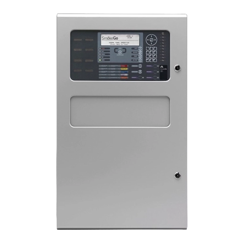
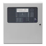
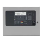
The Advanced SmokeGo 2-8 Loop Smoke Control Panel delivers complete and active smoke control directly integrated with fire alarm systems, designed for standalone, dedicated and non-dedicated Control and Indicating Equipment (CIE) applications. This sophisticated panel provides automatic and manual control of smoke control fans and dampers, ensuring compliance with the most stringent smoke management standards including EN54 Parts 2 & 4, ISO 21927-9 and BS7346-8.
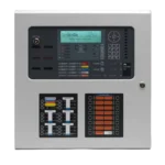
Featuring a high-resolution graphical LCD and tactile keypad, the panel offers intuitive ‘select & click’ programming for both engineers and end users. The system comes equipped with a single loop-driver card as standard, 2 onboard sounder circuits, 20 programmable zonal LEDs with slide-in labels, 25 system LEDs for status information, and 4 programmable function buttons with LED confirmation. The unique PC-NET-022 configuration software employs a graphical software matrix that simplifies system setup through visual representations and drop-down menus, making programming both quick and intuitive.
Expandable from 2 to 8 loops via plug-in loop driver boards, the panel supports Apollo XP95/Discovery, Hochiki ESP and AxisEn protocols. Fan and damper switch cards can be fitted internally or externally, with up to 15 cards supported per peripheral bus (P-Bus), enabling the control of 500 smoke compartments and 2000 dampers. The panel is compatible with AdvancedLive (UK&I only) for secure, real-time remote monitoring, and can be networked with other SmokeGo or MxPro 5 panels via optional network cards to create true peer-to-peer systems in fault-tolerant loop or radial configurations supporting up to 2000 zones.
Features
- Fully expandable from 2 to 8 loops via plug-in loop driver boards for scalable installations
- EN54-2:1997 +A1:2006 and EN54-4:1997 +A1:2002 +A2:2006 certified by FM Approvals
- Designed to comply with ISO 21927-9 and BS7346-8 smoke control standards
- Graphical LCD user interface with 240 x 64 white backlit display for clear visibility
- 20 programmable zonal LEDs and 20 system LEDs with slide-in labels for easy identification
- 5 dedicated smoke control LEDs for at-a-glance system status monitoring
- Dedicated loop driver support for Apollo XP95/Discovery, Hochiki ESP or AxisEn protocols
- Supports up to 200 fire zones by default with expansion to 2000 zones when networked
- Controls 500 smoke compartments and 2000 dampers for comprehensive smoke management
- Dual flash-based microprocessor technology with real-time clock onboard for reliable operation
- PC-NET-022 configuration software with unique software matrix for intuitive programming
- Auto-learn, loop detection and onboard scope facility for simplified commissioning and fault finding
- Fully programmable via onboard alphanumeric keypad or PC configuration tools
- 8 x 1 Amp programmable onboard sounder circuits for alarm notification
- 4 x 1 Amp programmable onboard relays expandable to 8 using 2 x Mxp-507 cards
- Up to 15 fan and damper switch cards per P-Bus for extensive system expansion
- Dedicated USB and RS232 serial ports for direct PC or modem connection
- AdvancedLive connectivity (UK&I only) with Ethernet connection onboard for remote monitoring
- Advanced peer-to-peer networking supporting up to 2000 zones across multiple panels
- Fault-tolerant loop or radial network configuration options available
- Graphical display configurable for virtually any language or character set
- Installer logo application support using dedicated Logo software
- Robust removable equipment chassis with plug-in connectors for simplified installation
- Comprehensive event logging with 2 x 5000 event & diagnostic plus 500 fire event capacity
- Temperature compensated battery charging with 2 x 2.0A charger current
- Optional on-board printer support for hard copy event documentation
- Multiple metalwork options including flushing bezel, battery box, utility enclosure and rack mount
Video
What is the primary cause of fire-related deaths?
Smoke inhalation is the primary cause of fire-related deaths, making effective smoke control systems essential for life safety in buildings.
Why is controlling the flow of smoke important in a fire?
Controlling the flow of smoke is vital to create safe escape routes for occupants and clear access for firefighters. Proper smoke management ensures that evacuation paths remain tenable and that emergency responders can safely enter the building to tackle the fire.
What is SmokeGo from Advanced?
SmokeGo from Advanced is the UK’s first smoke control panel approved to EN54 Parts 2 and 4 by FM Approvals. It represents a significant advancement in smoke control technology, combining compliance with intuitive operation and comprehensive control capabilities.
How does SmokeGo simplify smoke management?
SmokeGo simplifies smoke management by providing complete control of fans and dampers directly from the fire system. The panel makes smoke control simpler to install, configure and operate through a simple four-step configuration process, eliminating the complexity traditionally associated with smoke control system setup.
What is the configuration process for SmokeGo?
The configuration process involves inputting the number of smoke compartments, assigning fire detection zones per compartment, and defining loop devices for smoke control. The system’s programming wizard automatically configures fan and damper interfaces, dramatically reducing the time and technical expertise required for system commissioning.
How does SmokeGo reduce setup time?
SmokeGo uses a unique mapping matrix, graphical system representations, drop-down menus and keyboard shortcuts to reduce setup time significantly. This intuitive approach enables creation of a working system in minutes instead of days, making installation more efficient and reducing project timescales.
What manual and automatic options does SmokeGo offer?
SmokeGo offers integrated and independent switch cards for manual and automatic control options that meet the requirements of virtually any site. This flexibility ensures the system can be configured to match specific building requirements and operational procedures, whether for standalone operation or full integration with the fire alarm system.
What is the post alarm purge feature in SmokeGo?
The post alarm purge feature rapidly clears smoke from a building after a fire event, enabling faster return to normal operations and reducing smoke damage. The feature can be automatically configured or manually controlled via an enable purge button or switch, giving operators full control over the purge process.
How does SmokeGo ensure safe evacuation and access for fire crews?
SmokeGo provides versatile programming options for stairwell pressurization to ensure safe evacuation of occupants and access for fire crews. By maintaining positive pressure in escape routes, the system prevents smoke ingress into critical evacuation paths, keeping them clear and safe during emergency situations.
Can SmokeGo prioritize smoke containment and extraction in critical areas?
Yes, SmokeGo allows easy configuration of cascade options to prioritize containment and extraction of smoke in critical areas of a building. This enables system designers to create intelligent smoke control strategies that respond to fire location and building layout, ensuring the most effective smoke management response.
What features help safeguard the SmokeGo system?
Features such as interlocks, sequential fan restart, group manual controls and automatic system tests for fans and dampers help safeguard the system and avoid overloading and damage. These protective features ensure long-term system reliability and prevent equipment failure during critical fire events.
Is SmokeGo compatible with different system types?
Yes, SmokeGo is compatible with dedicated and non-dedicated systems and can be networked or used independently. This versatility allows the panel to be specified for a wide range of applications, from standalone smoke control installations to large networked systems integrated with building-wide fire detection.
What additional monitoring capability does SmokeGo offer when used with AdvancedLive?
When used with AdvancedLive (UK & Ireland only), SmokeGo allows checking of fan and damper status remotely using any internet-enabled device. This provides facilities managers and service engineers with real-time visibility of system status without needing to be on site, enabling faster response to any issues and simplified system monitoring.
What are the key benefits of choosing SmokeGo from Advanced?
Key benefits include ultimate programming versatility to suit any building configuration, exceptional ease of use for both installers and end users, unbeatable setup times that reduce installation costs and project timescales, and complete fire safety peace of mind through robust EN54 certified smoke control functionality that meets the highest industry standards.
FAQs
What protocols does the SmokeGo 2-8 Loop Smoke Control Panel support?
The panel is available with dedicated loop driver support for three different protocols: Apollo XP95/Discovery (order codes SC-5802A series), Hochiki ESP (order codes SC-5802H series), or AxisEn (order codes SC-5802V series). Each panel is configured for a specific protocol, so you’ll need to specify which protocol matches your existing fire detection devices when ordering. The protocol determines compatibility with detectors, call points and other intelligent devices on the detection loops.
How many fan and damper switch cards can be connected to the panel?
The SmokeGo 2-8 Loop panel supports up to 15 fan and damper switch cards per peripheral bus (P-Bus), with each switch card capable of controlling up to 6 individual fans and dampers. These cards can be fitted either internally within the panel enclosure or externally using optional enclosures. This allows the system to manage up to 500 smoke compartments and 2000 dampers in total, providing comprehensive smoke control for even the largest and most complex building configurations.
What is the difference between standard and fault-tolerant network configurations?
Standard network configurations (order codes ending in A, H or V) use radial network topology where panels connect in a star or branched arrangement. Fault-tolerant configurations (order codes ending in A/FT, H/FT or V/FT) create a redundant loop topology where the network forms a complete ring. In fault-tolerant mode, if the network cable is cut or damaged at any point, communications continue flowing in the opposite direction around the loop, maintaining full system functionality. This provides enhanced reliability for mission-critical installations.
Can the panel be monitored and controlled remotely?
Yes, the panel is compatible with AdvancedLive (UK & Ireland only), which provides secure, real-time remote monitoring and management capabilities. With an Ethernet connection built into the panel, AdvancedLive enables remote checking of fan and damper status, receives instant notifications of events requiring attention, and allows essential system tasks to be performed without being on site. This significantly enhances system visibility and enables faster response to any issues, whilst also providing proof of servicing through downloadable service reports.
What battery backup options are available for the panel?
The panel accommodates flexible battery backup configurations to suit different standby power requirements. Internal battery capacity ranges from a minimum of 2 x 24V 4Ah batteries up to a maximum of 2 x 24V 18Ah batteries. For extended standby times, the system can support 1 x 24V 45Ah battery internally combined with 1 x 24V 45Ah battery in an optional external battery enclosure. The panel features temperature compensated charging at 2 x 2.0A to maintain optimal battery condition and maximise operational life.
How is the panel programmed and configured?
Programming is accomplished through two convenient methods. Engineers can configure the system directly on-site using the onboard alphanumeric keypad with the intuitive graphical LCD interface providing ‘select & click’ navigation. Alternatively, the PC-NET-022 configuration software offers a more comprehensive programming environment with a unique graphical software matrix, drop-down menus and visual system representations that make complex configurations quick and intuitive. The panel connects to a PC via dedicated USB or RS232 serial ports for configuration, diagnostics and firmware updates.
What expansion options are available beyond the standard configuration?
The panel offers extensive expansion capabilities through its integral P-Bus (peripheral bus) system. Beyond the standard 4 onboard programmable relays, you can add 2 x Mxp-507 cards to expand to 8 relays total. The system supports multiple option cards for additional functionality including network cards for panel-to-panel communication, BMS interfaces, graphical interfaces, and additional I/O modules. When networked, the system can connect up to 200 network nodes supporting 2000 fire detection zones, and fan/damper control can be expanded via up to 15 switch cards per P-Bus for controlling 500 smoke compartments and 2000 dampers.
Specifications
- Base Technology: Dual flash-based processors with real-time clock, trace diagnostics, programmable languages and character sets
- Display: White backlit 240 x 64 graphical LCD
- LED Indicators: 22 red (1 x Fire, 1 x More Alarms, 20 x Zonal Programmable), 1 green (Power), 13 amber and 7 bi-colour (Fault & System)
- Controls: Alpha numeric keypad permitting Navigation, Reset, Mute, Silence, Resound, Evacuate, and 4 x Programmable Push Buttons
- Protocols: Apollo (XP95 / Discovery), Hochiki ESP & AxisEn
- Number Of Fire Zones: 2000 when networked (400 max across 8 loops)
- Number Of Loops: Dedicated 2-8 loop control panel
- Devices Per Loop: Protocol dependent
- Loop Current: 500mA max per loop
- On-Board Sounder Circuits: 8 x 1 Amp programmable
- On-Board Relays: 4 x 1 Amp 30v AC/DC programmable (10mA, 5v min) – expandable to 8 using 2 x Mxp-507
- Auxiliary Supply: 2 x 24v 500mA
- Programmable Input: 2 x On-board Programmable Input
- Programmable Key Switch Inputs: 16 volt free digital inputs
- Total Available Output Current: 2 x 5A maximum available for loop current + sounder outputs + auxiliary supply
- Mains Supply: 200 – 240v 47-63 Hz AC (+10%, -15% tolerance) 1.4A max
- Battery Capacity: 2 x 24V 4Ah internal (min), 2 x 24V, 18Ah internal (max), or 1 x 24V 45Ah internal (max) and 1 x 24V 45Ah external (max) using optional battery enclosure
- Charger Current: 2 x 2.0A temperature compensated
- Ethernet Port: 10-Base-T, 100-Base-T: AdvancedLive connectivity (UK&I)
- Serial Ports: 2 x on-board RS232 connection for PC, modem, IP or portable printer
- USB Interface: 2 x USB B type connection for PC communication
- Programming: On-board keypad or PC running Windows tools
- Event Log: 2 x 5000 Event & Diagnostic + 500 Fire
- Printer (Optional): On-board
- Enclosure / Colour: Steel IP30 / RAL7035
- Cable Entry (20mm Knockouts): 30 x top, 6 x rear, 3 x bottom plus 2 x double knockout rear
- Extended – Size H X W X D Mm: 750 x 450 x 190
- Metalwork Options: Flushing bezel, battery box, utility enclosure, termination enclosure and rack mount
- Smoke Compartments: 500
- Dampers: 2000
- Fan/Damper Switch Cards: Up to 15 per P-Bus
- Approvals: EN 54-2:1997 +A1:2006, EN 54-4:1997 +A1:2002 +A2:2006 (FM Approvals)
- Compliance Standards: ISO 21927-9 and BS7346-8
Additional information
| Weight | 1 kg |
|---|---|
| Protocol | |
| Network Card | Standard, Fault-Tolerant |
| Device Type |
More Control Panel products from Advanced
Advanced Go Single Loop Fire Panel
Advanced MxPro 5 – 1 Loop Panel
Advanced MxPro 5 – 4 Loop Panel
Advanced MxPro 5 – 8 Loop Panel
Advanced MxPro 5 – 2 Loop Panel
Advanced QuickZone XL Conventional or Sav-Wire Panel
Advanced SmokeGo Control Panel | 1-2 Loop Expandable Smoke Control System | Apollo, Hochiki & AxisEn Protocol Options