


Ziton ZP752-2 | Addressable Line Sounder Driver | 2 Monitored Circuits, Surface Mount
£78.54 (inc VAT: £94.25)
Summary
The Ziton ZP752-2 is an addressable monitored dual output module providing two conventional alarm circuits for operating polarized sounders and visual indicators in Ziton addressable fire alarm systems. Both Output 1 and Output 2 share the same addressable loop address and operate simultaneously, providing synchronized alarm signaling across multiple sounder circuits. The module can be programmed to activate from a single address, groups or zones of devices, or as a common output triggered by any device connected to the system.
Power for the alarm circuits is supplied either from an external EN54-4 compliant power supply (22-30VDC) or directly from the panel’s 24VDC supply via separate wiring, with each circuit capable of delivering up to 1A at 24VDC. The ZP752-2 continuously monitors its power supply and automatically reports any failures to the main control panel, including mains failure, battery issues, or loss of 24VDC output. Each output circuit is protected by a monitored 1A fuse, with both open circuit and short circuit faults detected via 2.2kΩ end-of-line resistors.
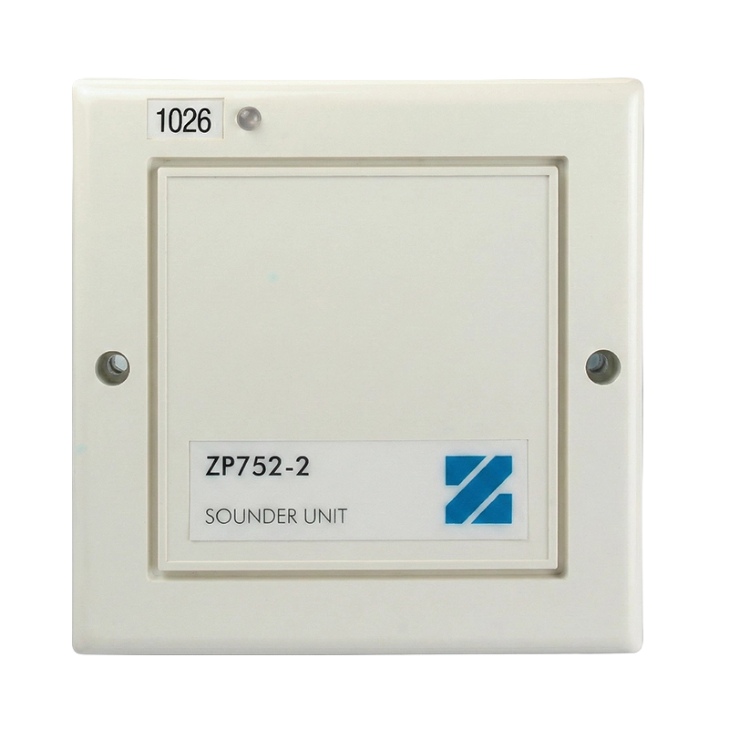
Designed for first and second fix installation, the module comprises a backbox containing all wiring terminals and a front plate housing the electronics and DIP switch for address configuration. A tri-colour LED on the front plate provides clear status indication: off for normal condition, red for active alarm, and amber for fault conditions. Up to 127 ZP752-2 units can be connected to a single ZP loop. For BS5839-1 compliant systems requiring sounder response within 3 seconds of manual call point operation, up to 16 ZP752-2 modules assigned to the first 16 loop addresses can achieve this critical response time. The module is EN54-18 certified with CPR compliance and housed in a white moulded ABS enclosure suitable for indoor surface mounting.
Features
- Addressable dual output module for two conventional sounder/visual indicator circuits
- Compatible with all Ziton ZP addressable fire alarm systems
- Both output circuits share single addressable loop address (1-127)
- Outputs operate simultaneously – cannot be activated independently
- Programmable activation from single address, device groups, zones, or system-wide trigger
- Dual power options: external 22-30VDC supply or direct from panel 24VDC output
- Each output circuit delivers 1A at 24VDC maximum
- Each circuit protected by monitored 1A fuse
- Low current consumption: 400µA standby, 600µA activated (loop), up to 1A external supply as required
- Continuous monitoring of external power supply status
- Automatic fault reporting for mains failure, battery issues, or 24VDC loss
- Monitors connected devices for open circuit and short circuit faults
- 2.2kΩ end-of-line resistor per circuit for fault supervision
- Supports polarized sounders and visual indicators (polarity reverses when inactive)
- Non-polarized devices require 1N4002/7 diode in positive leg (stripe facing device)
- Optional power supply supervision relay input for enhanced monitoring
- Tri-colour LED status indicator: off (normal), red (active alarm), amber (fault)
- Red LED illuminates when both sounder circuits activated
- Amber LED illuminates for circuit faults or power supply issues
- Seven-segment DIP switch for binary address configuration
- Address range: 001 to 127 on addressable loop
- Up to 127 ZP752-2 modules per loop maximum
- First 16 addresses (1-16) support 3-second response for BS5839-1 compliance
- Meets manual call point response time requirement within 3 seconds
- Status polled by control panel every 2 seconds
- Two-part construction: backbox with terminals and plug-in front plate with electronics
- First and second fix installation capability
- Backbox contains all field wiring screw terminals
- Front plate houses electronics, PCBs and address DIP switch
- Knockouts on backbox for conduit box mounting
- Space for address label on top left of front plate
- Programmable for continuous or pulsed output operation
- Maximum line drop: 2V for reliable operation
- Two-core screened loop wiring connection
- Two-core spur wiring for each sounder circuit
- Three-core power supply connection (positive, negative, monitor)
- White moulded ABS construction
- Compact surface mount design: 120mm wide × 120mm high × 40mm deep
- Weight: 310g for easy installation
- Operating temperature range: -10°C to +55°C (some sources indicate up to +75°C)
- Storage temperature range: -10°C to +70°C
- Relative humidity: 10% to 95% non-condensing (some sources indicate 20% to 95%)
- Indoor use application
- IP42 environmental protection rating (some sources indicate IP40)
- EN54-18:2005 certified for input/output devices
- CPR (Construction Products Regulation) compliant
- CE marked for EMC compliance (EEC89/336)
- Module will not operate without electrical power – backup power recommended
FAQs
Can the two output circuits be controlled independently?
No, both Output 1 and Output 2 on the ZP752-2 share the same addressable loop address and therefore switch on and off simultaneously. The two circuits are linked and cannot be activated independently. If independent control of two separate sounder circuits is required, two separate ZP752-2 modules with different addresses would need to be installed. However, having both circuits operate together from a single address is typically the desired configuration for providing synchronized alarm signaling across multiple zones or floors of a building from one trigger source.
How many ZP752-2 modules can be installed on one loop?
Up to 127 ZP752-2 modules can be connected to a single ZP addressable loop, as the Ziton protocol supports a maximum of 127 addresses per loop. However, for systems that must comply with BS5839-1 requirements where sounder response to manual call point operation must occur within 3 seconds, only the first 16 ZP752-2 modules assigned to addresses 1-16 on the loop can guarantee this response time. The faster response for lower addresses is due to the sequential polling nature of addressable systems – devices with lower addresses are polled earlier in each 2-second cycle.
What power supply options are available for the ZP752-2?
The ZP752-2 offers dual power supply options for its conventional output circuits. Power can be supplied from an external EN54-4 compliant power supply rated at 22-30VDC, which is the recommended option for reliability and system integrity. Alternatively, power can be drawn directly from the fire alarm panel’s 24VDC auxiliary supply via separate wiring. The module itself draws 400µA standby and 600µA when activated from the addressable loop for monitoring and control, while the external supply or panel auxiliary output provides the higher current (up to 1A per circuit) needed to drive the connected sounders and visual indicators.
What types of devices can be connected to the output circuits?
The ZP752-2 is designed to operate polarized sounders and visual indicators, where the device polarity must be observed during installation. The terminal markings (plus/minus) indicate signal polarity when the circuit is active – notably, the polarity reverses when the circuit is inactive, which is how the module monitors for faults. If non-polarized devices need to be used, a 1N4002 or 1N4007 diode must be inserted in the positive leg of each device with the stripe on the diode facing toward the device. Each circuit can deliver up to 1A at 24VDC, sufficient for multiple sounders or combined sounder/beacon units.
How does fault monitoring work on the ZP752-2?
The ZP752-2 provides comprehensive fault monitoring for both the power supply and connected output circuits. Each output circuit requires a 2.2kΩ end-of-line resistor which enables the module to detect both open circuit faults (wiring break or device disconnection) and short circuit faults (wiring shorted together). The module also monitors the external power supply or panel auxiliary supply, reporting any mains failure, battery issues, or loss of the 24VDC output to the control panel. Additionally, each circuit is protected by a monitored 1A fuse – if a fuse blows, this fault is also detected and reported. All faults are indicated by the amber LED on the front plate and reported to the control panel with the module’s address.
What does the LED indicator show?
The ZP752-2 features a tri-colour LED status indicator on the front plate that provides clear visual feedback of the module’s operational status. When the LED is off, the module is in normal standby condition with no alarm and no faults. The red LED illuminates when the module is activated and both sounder circuits are energized, confirming alarm operation. The amber LED illuminates when a fault condition is detected, which could include open or short circuit faults on either output circuit, power supply failure, fuse blown, or other monitored fault conditions. This local indication supplements the detailed fault reporting sent to the main control panel.
How is the address set on the ZP752-2?
The ZP752-2 uses a seven-segment DIP switch (SW1) for address configuration using binary coding. Each switch segment has a decimal value: switch 1 = 1, switch 2 = 2, switch 3 = 4, switch 4 = 8, switch 5 = 16, switch 6 = 32, and switch 7 = 64. The device address is calculated by adding the values of all switches set to ON. For example, to set address 007, switches 1, 2, and 3 should be ON (1 + 2 + 4 = 7) with all other switches OFF. Any address from 001 to 127 can be configured, but each address must be unique on the loop. For fastest response to manual call points, use addresses 1-16.
What is the purpose of the power supply supervision relay input?
The ZP752-2 includes an optional input for connecting a supervision relay from the external power supply. Many EN54-4 compliant power supplies include a relay output that monitors the status of the power supply – typically the relay is closed (short-circuit) when the power supply is operating correctly. If your external power supply has this feature, connect the supervision relay contacts to the designated input terminals on the ZP752-2. This enables the module to actively monitor power supply health and report any issues to the control panel. If your power supply does not have a supervision relay, this input should be short-circuited (jumpered) to avoid generating a false fault indication at the module.
Specifications
- Product Code: ZP752-2 (13810-ZT)
- Type: Addressable monitored dual output module
- Compatibility: All Ziton ZP addressable fire alarm systems
- Certification: EN54-18, CPR certified
- Output Circuits: 2 conventional circuits (simultaneous operation)
- Output Current Per Circuit: 1A at 24VDC maximum
- Circuit Protection: 1A monitored fuse per circuit
- End Of Line Resistor: 2.2kΩ (2K2) per circuit
- Operating Voltage (External Power): 22 to 30 VDC
- Operating Voltage (Loop Power): 20V pulsed analogue loop (16 to 22 VDC)
- Maximum Line Drop: 2V
- Current Consumption (Standby): 400µA (loop)
- Current Consumption (Activated): 600µA (loop)
- External Supply Current: Up to 1A as required, 700µA typical
- Addressing Method: 7-segment DIP switch (binary coding)
- Address Range: 001 to 127
- Maximum Modules Per Loop: 127
- Fast Response Addresses: First 16 addresses support 3-second response for BS5839-1 compliance
- Status Polling Interval: Every 2 seconds by control panel
- Status Indication: Tri-colour LED – off (normal), red (alarm active), amber (fault)
- Monitoring (Module): Loop address, external power supply status
- Monitoring (Connected Devices): Open and short circuit via EOL resistor
- Monitoring (Fuses): Fuse status monitored and reported to panel
- Device Polarity: Polarized sounders required (polarity reverses when inactive)
- Non-polarized Device Support: Requires 1N4002/7 diode in positive leg
- Power Supply Supervision: Optional relay input for external PSU monitoring
- Wiring (Loop Interface): Two-core screened cable
- Wiring (Sounder Circuits): Two-core spur per circuit
- Wiring (Power Supply): Three-core (positive, negative, monitor)
- Construction: Two-part design – backbox and front plate
- Backbox: Contains all field wiring screw terminals
- Front Plate: Houses electronics, PCB, DIP switch
- Installation Type: First and second fix capability
- Mounting Type: Surface mount with conduit box knockouts
- Material: Moulded ABS
- Colour: White
- Dimensions (W × H × D): 120 × 120 × 40mm
- Weight: 310g
- Operating Temperature: -10°C to +55°C
- Storage Temperature: -10°C to +70°C
- Relative Humidity: 10% to 95% non-condensing
- Application: Indoor use
- IP Rating: IP42 (EN60529)
- EMC: CE marked (EEC89/336)
- Power Supply Compliance: External supply must be EN54-4 compliant
- Address Label Space: Top left of front plate
- Manufacturer: KGS Safety System (Hebei) Co. Ltd., China
- EU Representative: KGS Fire & Security B.V., Netherlands
- Notified Body: 0370
- Declaration Of Performance Number: 10-5221-360-0299
- Year Of First CE Marking: 2023
Downloads
- Datasheet (Adobe PDF)
- Installation Manual (Adobe PDF)
Additional information
| Protocol |
|---|